
Rebar Calculator: Estimating Steel Reinforcement, Weight, Spacing, and Lap Splices
Concrete is an exceptional material for withstanding compressive loads, but it is notoriously weak under tension. To prevent structural cracking and failure under bending forces, steel reinforcing bars (rebar) are cast inside the concrete. This creates reinforced concrete, a composite material that utilizes the strengths of both steel and concrete.
Estimating rebar accurately is critical for project budgeting and structural safety. Under-reinforcing can lead to catastrophic failure, while over-reinforcing increases costs unnecessarily. This Rebar Calculator helps engineers, contractors, and architects estimate the length, weight, and count of rebar needed for concrete elements, supporting both 2D grid layouts (for slabs and walls) and 1D linear layouts (for beams, columns, and strip footings).
The calculator supports two main modes: a Grid Estimator that calculates vertical and horizontal meshes, and a Linear Estimator that sizes longitudinal main reinforcement alongside optional stirrups/ties. It supports standard US (Imperial #3 to #18) and Metric (8mm to 40mm) rebar sizes, automatically computing nominal weights and incorporating lap splices and material waste.
Why Concrete Needs Steel Reinforcement
Unreinforced concrete has high compressive strength but very low tensile strength (typically only 10% of its compressive strength). When loaded, concrete beams, slabs, and footings experience bending moments that create tension zones on one side. Steel rebar, having high tensile strength, is placed in these tension zones to take up the tensile forces.
Furthermore, steel and concrete expand and contract at nearly identical rates under temperature fluctuations (having similar coefficients of thermal expansion). This compatibility prevents internal stresses from tearing the composite material apart over time.
Concrete Cover: Protecting Steel from Environmental Degradation
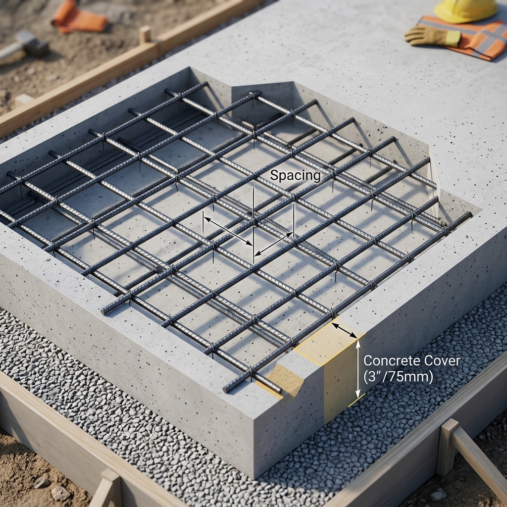
Concrete cover is the distance from the outer surface of the concrete to the nearest edge of the embedded steel rebar. Adequate cover is critical for two reasons:
- Corrosion Protection: Steel rusts when exposed to moisture and oxygen. Concrete is naturally alkaline, which creates a passivation layer on the steel. Thick concrete cover acts as a physical barrier preventing corrosive agents from reaching the steel.
- Fire Resistance: Concrete is a poor conductor of heat. Sufficient cover insulates the steel rebar, preserving its structural integrity during a fire.
Standard building codes (like ACI 318 or Eurocode 2) mandate minimum concrete covers based on exposure conditions:
- Cast against and permanently in contact with earth: 3 inches (75 mm)
- Exposed to earth or weather: 1.5 to 2 inches (40 to 50 mm)
- Not exposed to weather (inside buildings): 0.75 to 1.5 inches (20 to 40 mm)
Understanding Lap Splices and Standard Bar Lengths
Steel rebar is manufactured in standard stock lengths (commonly 20 feet or 40 feet in the US, and 6 meters or 12 meters in metric regions). When a concrete element is longer than the standard stock bar, two or more rebars must be joined. The most common joint is a lap splice, where two parallel bars overlap for a specified length to transfer the load across the joint.
The required lap splice length depends on the bar size, concrete grade, and structural design. A common rule of thumb is 40 to 50 times the bar diameter. For example, a #4 bar (0.5-inch diameter) with a 40d splice requires 20 inches of overlap. A 12mm bar with a 40d splice requires 480mm of overlap.
Number of Splices per Run = ceil(Effective Length ÷ Stock Bar Length) - 1
How Rebar Length and Weight are Calculated
Rebar weight is calculated by multiplying the total length of all bars by the nominal weight per unit length of the selected bar size.
For a Slab Grid, the slab length and width are first reduced by twice the concrete cover. The number of grid lines is determined by dividing this effective dimension by the spacing, adding 1 for the end bar. The total length of rebar is calculated for both directions, adding lap splices for any run exceeding the stock bar length, and then applying a waste percentage multiplier.
For a Linear Element (e.g. a beam), the number of main longitudinal bars is multiplied by the run length (accounting for cover and splices). If Stirrups (Ties) are added, their perimeter is calculated from the beam cross-section dimensions minus concrete cover, plus the length of two 135-degree hooks (typically 6d or 75mm minimum each). The number of stirrups is calculated by dividing the effective length by the stirrup spacing.
Slab Dimensions = 6.0m × 8.0m
Concrete Cover = 50mm (0.05m)
Bar Spacing = 200mm (0.2m)
Rebar Size = 12mm (Metric, 0.888 kg/m)
Effective Dimensions = 5.9m × 7.9m
Bars Parallel to 6.0m side: floor(7.9 / 0.2) + 1 = 40 runs of 5.9m = 236m
Bars Parallel to 8.0m side: floor(5.9 / 0.2) + 1 = 30 runs of 7.9m = 237m
Total Length: 236m + 237m = 473m (assuming no splices needed)
Total Weight: 473m × 0.888 kg/m = 420.0 kg (926.0 lbs)
Frequently asked questions
What do the rebar numbers (#3, #4, #5, etc.) mean?
In the US Imperial system, rebar sizes are designated by a number that represents the bar diameter in eighths of an inch. For example, a #3 bar is 3/8 inch in diameter, a #4 bar is 4/8 (1/2) inch in diameter, and a #8 bar is 8/8 (1) inch in diameter.
How do you calculate rebar weight per meter or foot from scratch?
For metric rebar, the weight can be estimated using the formula: Weight (kg/m) = (Diameter in mm)² ÷ 162. For Imperial rebar, the weight is: Weight (lb/ft) = (Diameter in eighths of an inch)² ÷ 24.
What is the purpose of rebar stirrups/ties?
Stirrups (also called ties in columns) are loops of steel wrapped around the main longitudinal bars. They resist shear forces in beams and prevent individual longitudinal bars from buckling outward in columns, while holding the main rebar cage together during concrete pouring.
How much rebar waste should I expect?
A standard waste allowance of 10% is recommended for slab grids to account for cutting scrap and overlaps. For simple linear beams or columns where bar lengths line up well with stock sizes, 5% is usually sufficient.